FRP Columns is a comprehensive analysis and design software for concrete columns reinforced with FRP bars. It is designed and tested for rectangular, circular, and elliptical column sections. It enables the generation of limit and design interaction diagram for short columns, considering biaxial bending plus axial compression forces in accordance with ACI 440.11-22. The user also has the option to analyze and design slender columns by including the slenderness effect in accordance with the ACI moment magnifier method. The software is further complemented by including the option of conducting shear analysis for slender columns. The software operates in dual units SI and US customary units with full capability of switching back and forth between them. Furthermore, the software is supported by a professional design report consisting of input parameters and output results.
The software inputs are divided into material and geometrical properties, where every category covers the different properties for concrete and FRP. For the interaction diagrams, the user can select to plot limit, design, or both interaction diagrams at any desired slope angle of biaxial moment ratio. Moreover, the user can plot demand values to check whether they fall inside or outside the interaction diagrams. The software is further equipped with full consideration of slenderness effects in both directions with sway or no sway mode options and combinations thereof.
Platform: Windows
Version: 1.0.0
Custom-Built For: Sustainable Alliance Pty Ltd of South Australia
Dual Units
Dual units capabilities (US Customary units and SI units).
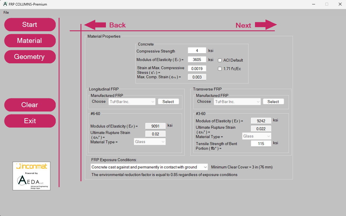
Complete Material Definition
Well-defined material parameters for concrete and FRP. The software supports a manufacturer library for FRP material properties.
Complete Geometry Definition
A complete definition for the geometry of the cross section (Rectangular, Circular and Elliptical), maximum aggregate size, and longitudinal and transverse FRP reinforcements.
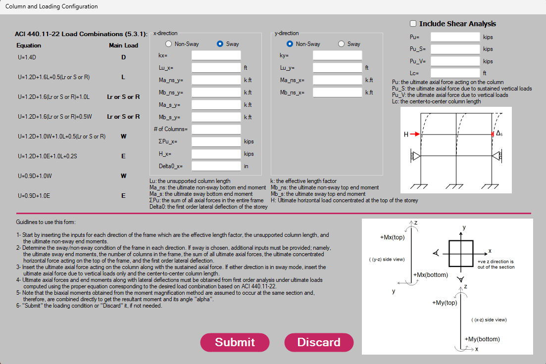
Slenderness Effect
The software can take into account the slenderness effect in accordance with the ACI moment magnifier method for sway and no-sway conditions. The user can also choose to include shear analysis.
Biaxial Bending Moment
The software takes into account the biaxial moment effect on the section from the x-direction and y-direction. The user can choose the slope angle of biaxial moment ratio corresponding to the desired interaction diagram.
Limit State Interaction Diagram
The software generates the limit state interaction diagram of the cross-section without accounting for the strength reduction factor.
Design State Interaction Diagram
The software generates the design state interaction diagram of the cross-section taking into account the strength reduction factor and all safety provisions in accordance with ACI 440.11-22.
Tabulated Data
Tabulated data of the interaction curves can be accessed for further investigations.
Demand Values
Up to 10 different demand values can be plotted to check the adequacy of the cross-section for them.
Magnified Load
The magnified load due to the slenderness effect is reflected on the interaction diagram as a design loading point to check if it is below or above the cross-section’s capacity.
Shear Analysis
If shear analysis is desired by the user, a summary of the results is presented upon plotting the interaction diagram.