FRP Column Confinement Analysis is a comprehensive software column analysis and design software. It enables the generation of limit and design interaction diagram for circular and rectangular short columns, considering biaxial bending plus axial compression-tension forces. The software is made powerful by adding the effect of FRP wrapping confinement. The user can select to plot different combinations of unconfined, FRP confined, unconfined design and confined design interactions diagrams, you can also quickily design concrete columns for longitudinal steel ratio as well as confinement FRP ratio through special utility tools.
Furthermore, the software is supported by a professional design report consisting of input parameters and output results. The software operates in dual units SI and US customary units with full capability of switching back and forth between them.
In the Premium version, the software is equipped with full consideration of slenderness effects in both directions with sway or no sway mode options and combinations thereof. The final product is very versatile in offering a wide range of load combinations, slenderness effects and analysis/design interaction diagrams.
Platform: Windows
Version: 1.1.0
Yearly subscription: 750$
Monthly subscription: 150$
License: one license/one computer
Complete Geometrical and material definition
The software inputs are divided into material and geometrical properties, where every category covers the different properties for concrete, steel and FRP.
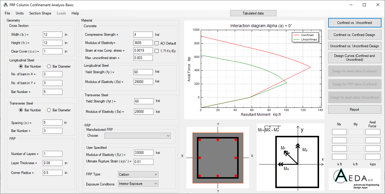
Fully developed interaction Diagrams
A complete interaction diagram between the biaxial resultant moment and tension-compression axial forces for rectangular and circular sections.
Biaxial Bending moment
The software takes into account the biaxial moment effect on the section from x-direction and y-direction,
Limit state interaction Diagrams
The software generates the limit state interaction diagram of the unconfined reinforced concrete section as well as the FRP confined section.
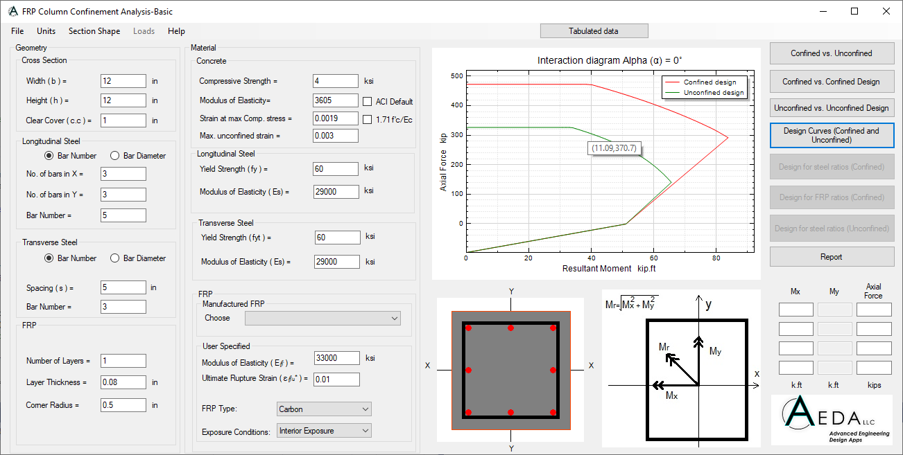
Design state interaction Diagrams
The software generated the design interaction diagrams for the confined and uncondined sections, taking into account all safety factors from ACI440.
Built-in library for FRP sheets
The software is equipped with FRP sheets properties for some of the common FRP manufacturers.
Tabulated data
Tabulated data of the interaction diagrams for further investigations.
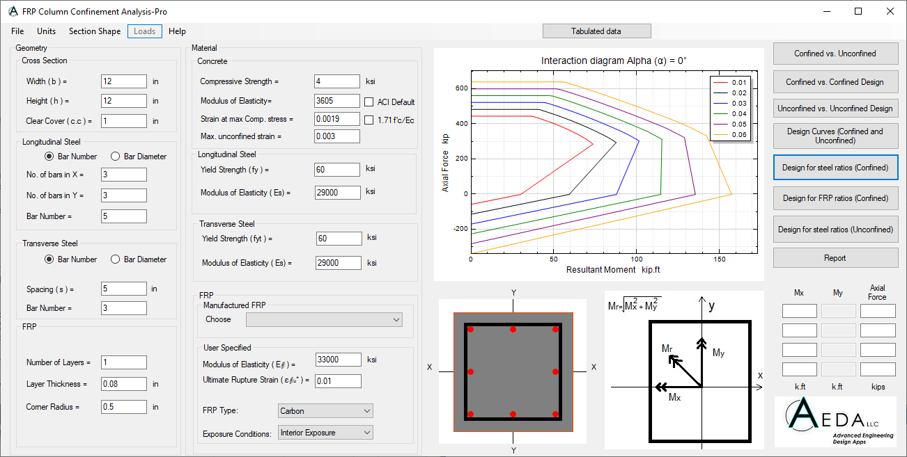
Design for different Steel ratios
For a constant ratio of FRP, the software generates multiple design interaction diagrams for different steel ratios.
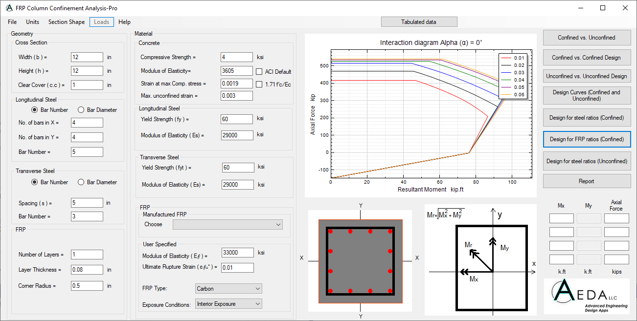
Design for different FRP ratios
For a constant ratio of steel, the software generates multiple design interaction diagrams for different FRP ratios.
Slenderness effect
The software takes into account the slenderness effect using the magnification factor effect for sway and no-sway conditionts.
Load Combinations
The user can choose from a wide variety of load combinations in accordance with ACI318.
Magnified load
The magnified load due to the slenderness effect is reflected in the interaction diagram as a design loading point. A point inside the interaction diagram indicates the ability of this column to handle the applied load.
Please, Login to purchase FRP Column Confinement Analysis Premium version.