UHPC Column: Ultra High Performance Concrete Column Analysis
UHPC Column: Ultra High Performance Concrete Column Analysis
UHPC Column delivers comprehensive analysis and design capabilities for reinforced ultra-high-performance concrete columns. Engineered and validated for rectangular, circular, and elliptical geometries, it generates limit and design interaction diagrams for short columns subject to biaxial bending and axial loads. Calculations comply with ACI 318-25 while incorporating tailored modifications specific to UHPC. Users can evaluate slender columns via the standard ACI moment magnifier method or a proprietary Advanced Method developed by our engineers. The platform natively supports dual units (SI and US Customary), enabling seamless, on-the-fly toggling. Efficiency is optimized through an automated utility that calculates required longitudinal reinforcement ratios. Finally, the software generates professional, client-ready design reports detailing all governing design criteria, inputs, and output summaries.
Software inputs are systematically categorized into material and geometric properties, with distinct sections for the specific attributes of concrete and steel. For interaction curve generation, users can generate limit and design interaction diagrams at any preferred slope angle of biaxial moment ratio. Additionally, the software allows users to plot demand values to visually verify whether they fall inside or outside the capacity curves. The program also features comprehensive options to account for slenderness effects in both directions, offering sway or non-sway mode selections and their combinations. Ultimately, the software provides great versatility by delivering an extensive range of load combinations, slenderness considerations, and design interaction curves.
Platform: Windows
Version: 1.0.0
Yearly subscription: $1000
Monthly subscription: $200
License: one license/one computer
Please, Login to purchase UHPC Column.
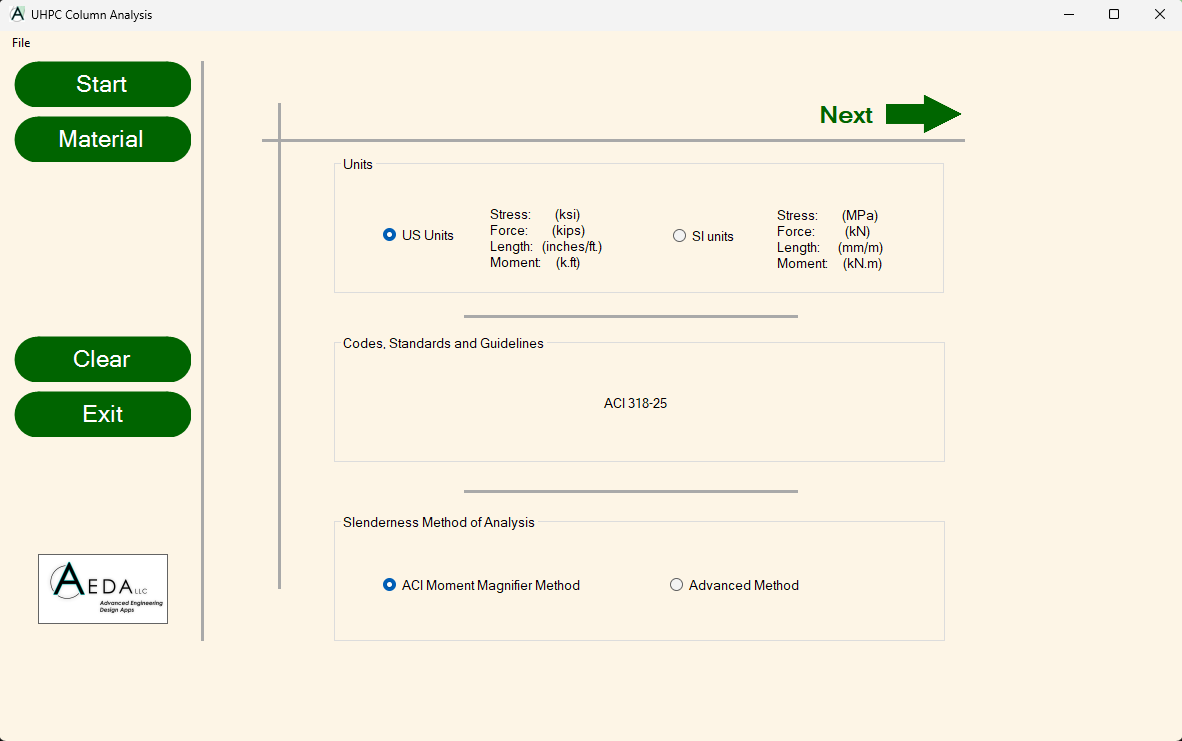
Dual Units
Supports dual unit systems, allowing seamless switching between US Customary and SI metrics.
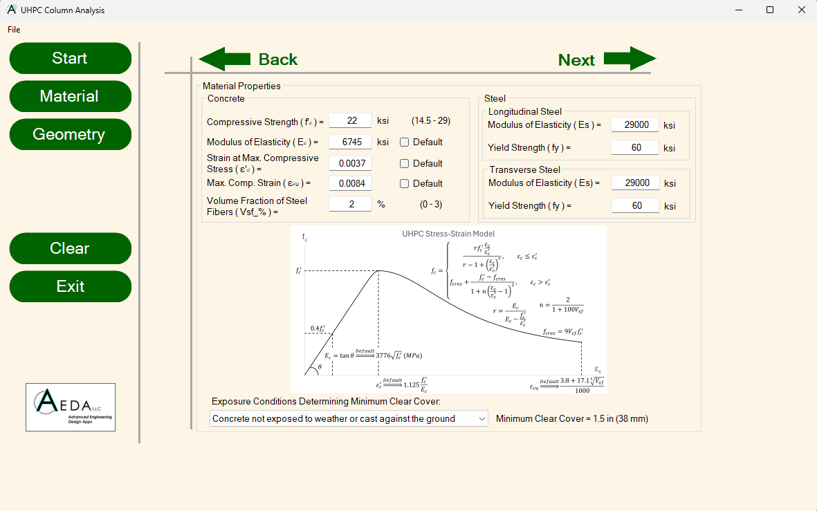
Complete Material Definition
Highly precise material property inputs for both concrete and steel reinforcement.
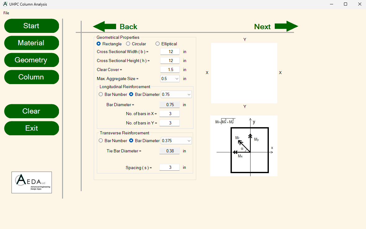
Complete Geometry Definition
Comprehensive definition criteria for cross-sectional geometries, including rectangular, circular, and elliptical profiles, alongside maximum aggregate size, longitudinal steel, and transverse reinforcement configurations.
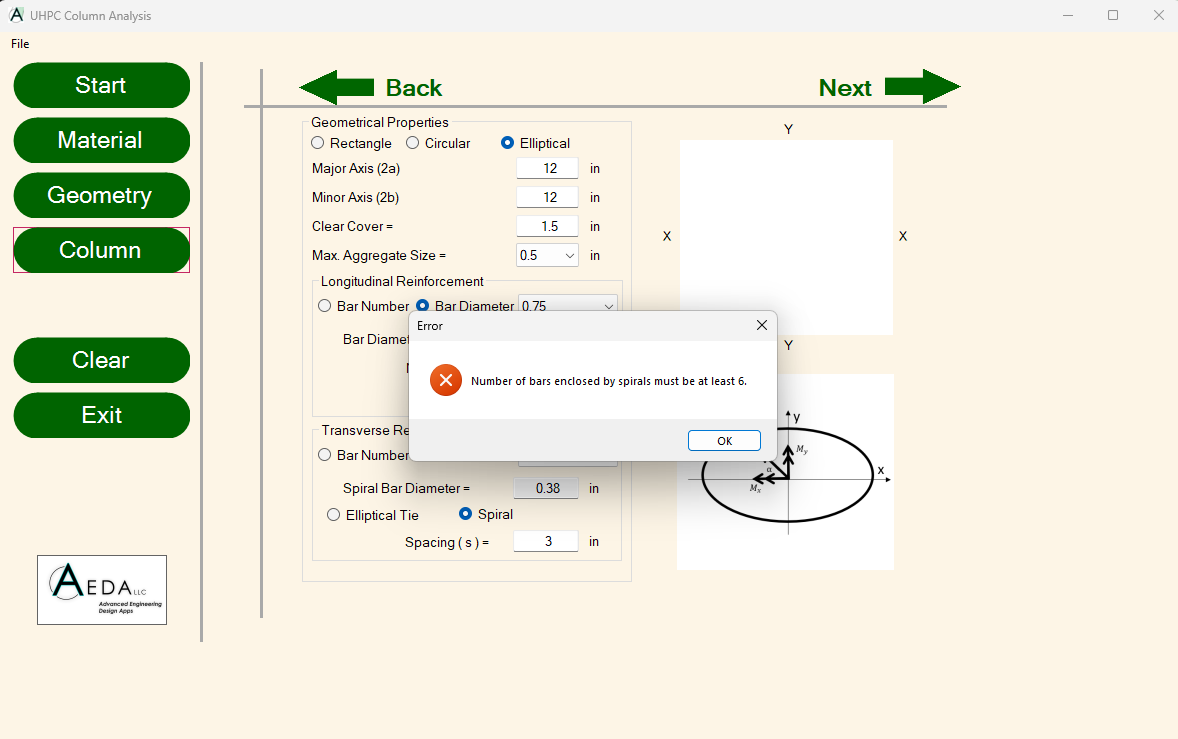
Errors and Warnings
The software integrates real-time error and warning notifications to systematically guide users in maintaining strict compliance with ACI code requirements and provisions.
Slenderness Effect
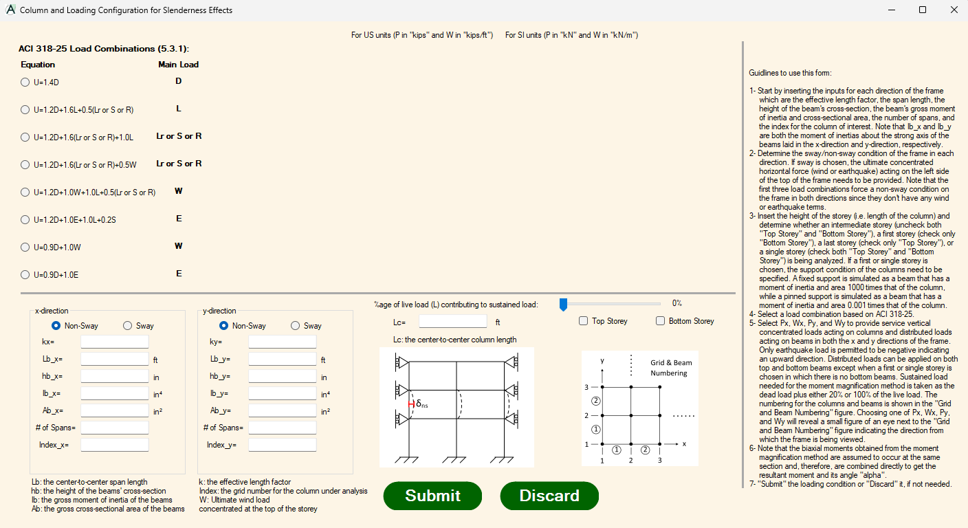
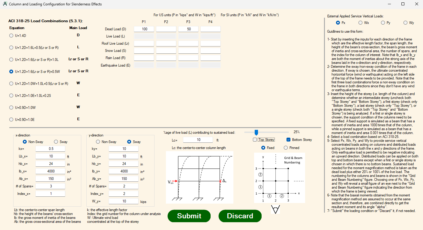
The software can take into account the slenderness effect in both directions with sway or no sway mode options and combinations thereof. It also offers a wide range of load combinations. To streamline data entry within the slenderness module, comprehensive step-by-step guidelines are integrated directly for the user.
Dual Methods for Slenderness Analysis
Slenderness analysis can be executed using either the standard ACI moment magnifier method or a proprietary advanced method formulated by the software developers. This proprietary approach delivers higher accuracy, particularly when evaluating sway frame configurations.
Complete Frame Analysis
To make the software more powerful, it features fully integrated first-order frame analysis capabilities, eliminating the necessity of secondary software to determine first-order moments. The analysis module accommodates up to seven continuous spans along each principal direction. Furthermore, the engine processes both uniformly distributed loads and concentrated point loads.
Biaxial Bending Moment
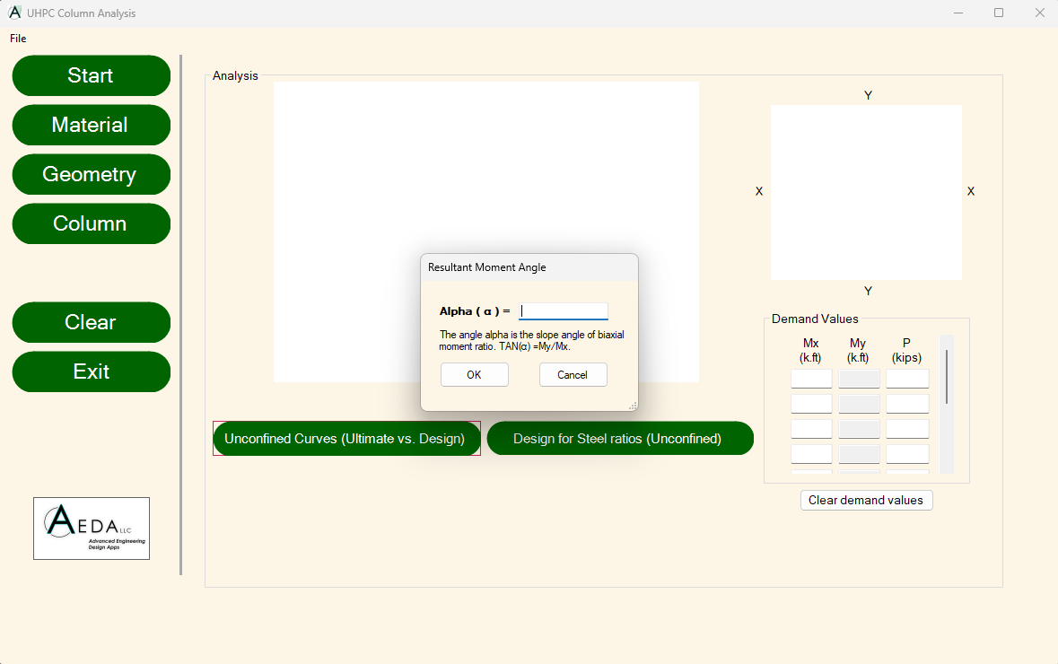
The software takes into account the biaxial moment effects acting on the cross-section from both the x-direction and y-direction. Users can select the specific slope angle of biaxial moment ratio to generate the corresponding directional interaction diagram.
Fully Developed Interaction Diagram
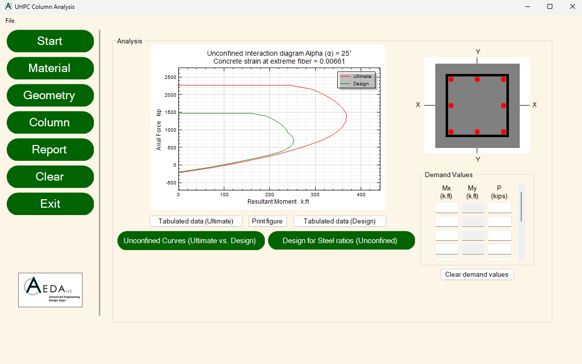
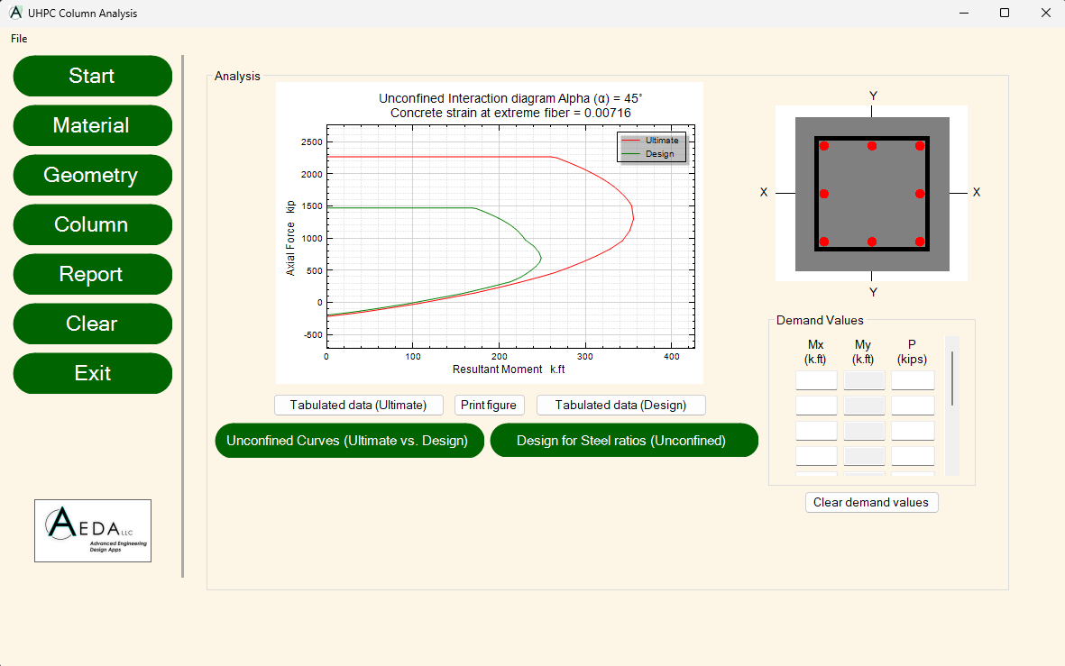
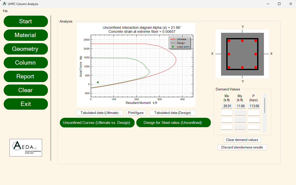
A comprehensive capacity interaction diagram mapping the relationship between the biaxial resultant moment and axial forces, including full coverage of the tension zone.
Limit and Design State Interaction Diagrams
The software generates the limit state interaction diagram of the cross-section without accounting for the strength reduction factor. It also generates the design state interaction diagram, taking into account applicable strength reduction factors and safety provisions according to ACI 318-25.
Design for Optimum Steel Ratio
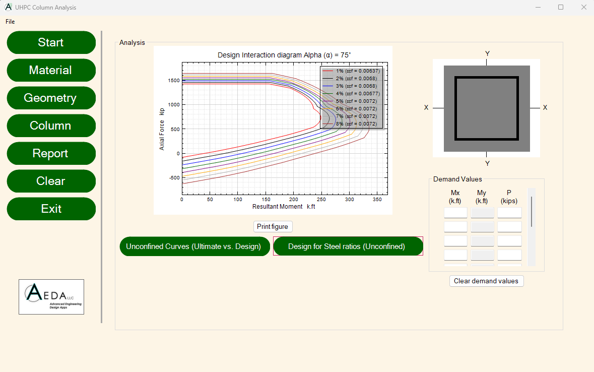
The software generates multiple design interaction diagrams across varying steel ratios. This significantly streamlines the selection process for identifying the optimum reinforcement ratio required to safely satisfy all engineering demand values.
Tabulated Data
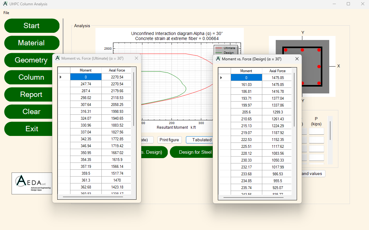
Tabulated interaction curve data can be readily accessed to conduct further engineering investigations.
Demand Values
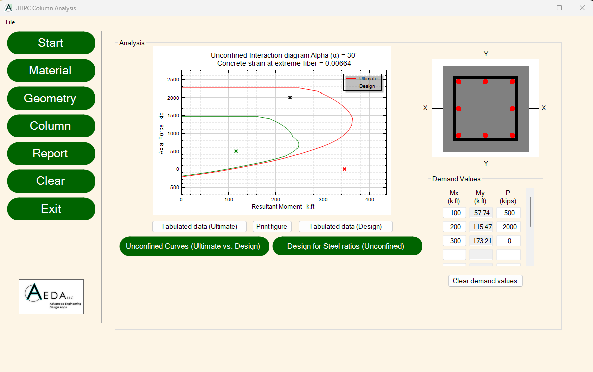
Up to 10 distinct demand values can be plotted simultaneously to visually evaluate cross-sectional adequacy. The specific color-coding of each plotted demand value immediately signals whether the cross-section possesses sufficient design capacity.
Magnified Load
The magnified load resulting from the slenderness analysis is mapped directly onto the interaction diagram as a design loading value, enabling immediate verification of whether it falls within or exceeds cross-sectional capacity limits.